
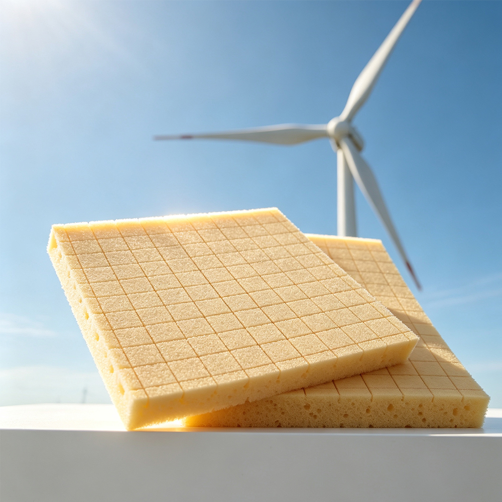
Wind Turbine Blade Material Qualification & Design Allowables Report
1. Executive Engineering Summary
Wind turbine blades are lightweight composite structures designed to withstand millions of cyclic load events over their service life. Within the blade shell, sandwich construction is widely used because a low-density core can separate the structural face sheets and substantially increase bending stiffness without adding excessive mass.
PVC Foam Core is one of the established polymeric foam options for sandwich structures used in wind turbine blades. Its engineering value does not come simply from having a low density. The more important question is whether the selected core can provide the required combination of:
- Core shear strength
- Core shear modulus
- In-plane compression resistance
- Through-thickness compression strength
- Skin-core bonding performance
- Fatigue resistance
- Machining quality
- Resin compatibility
- Dimensional stability
- Weight efficiency
- Manufacturing consistency
For wind turbine blades, density alone is not a sufficient material-selection criterion.
A 60 kg/m³ PVC Foam Core may provide attractive weight reduction, but a higher-density grade may be required in a high-load region where core shear, compression or local buckling governs the design. Conversely, using a high-density PVC Foam Core throughout the entire blade can unnecessarily increase blade mass and manufacturing cost.
The engineering objective is therefore:
Use the minimum practical core density that provides sufficient structural performance, manufacturing reliability and fatigue durability for each blade region.
Research on wind-turbine sandwich structures has demonstrated that both foam density and core machining configuration can significantly influence in-plane compression strength and failure behavior.
This makes PVC Foam Core selection a zoning and qualification problem, rather than simply a material purchasing problem.
2. Where PVC Foam Core Fits Inside a Wind Turbine Blade
A typical composite wind turbine blade contains several structurally different regions.
| Blade Region | Typical Structural Requirement | Core Function | Relative Core Demand |
|---|---|---|---|
| Main shell | Bending + compression/tension | Maintain skin separation | High |
| Spar cap vicinity | High axial load | Local structural support | Very High |
| Shear web | Shear + compression | Increase panel stiffness | High |
| Trailing edge | Buckling resistance + shape retention | Stabilize skins | Medium–High |
| Leading edge | Impact + aerodynamic shape | Structural support | Medium–High |
| Tip region | Low mass + aerodynamic shape | Lightweight support | Low–Medium |
| Root transition | High local stress | Local reinforcement | Very High |
| Tapered transition | Load transfer + geometric transition | Controlled stiffness transition | High |
This immediately shows why a single-density PVC Foam Core specification may be unsuitable for a large blade.
The core is part of a load-transfer system consisting of:
Fiber-reinforced face sheet → adhesive/resin interface → PVC Foam Core → opposite interface → opposite face sheet
A core that performs well as a bare material can still produce poor sandwich performance if:
- the surface is contaminated,
- the core is incorrectly machined,
- resin distribution is poor,
- bonding is incomplete,
- grooves contain excessive voids,
- the core is crushed during handling,
- density varies excessively,
- or the interface is weaker than the core itself.
ASTM C273 specifically notes that measured core shear performance is affected by the facing material, adhesive, fabrication method, core geometry, density, specimen preparation, conditioning and testing environment.
3. The Wind Blade Core Selection Triangle
For wind turbine blade design, three competing objectives dominate core selection:
3.1 Weight
Lower density reduces core mass.
3.2 Structural Performance
Higher density generally provides greater mechanical capability, particularly where compression, shear or local stability is critical.
3.3 Manufacturing Reliability
The core must be machinable, bondable and compatible with the infusion process.
Therefore:
Low Density ≠ Automatically Better
and
High Density ≠ Automatically Safer
The correct design approach is:
Optimize core density according to local structural load, geometry, fatigue requirement and manufacturing process.
4. Engineering Density Map for PVC Foam Core
The following ranges should be treated as an engineering selection framework, not universal material specifications. Actual allowable values must come from supplier test data and project-specific qualification.
| PVC Foam Core Density | Typical Engineering Position | Potential Application |
|---|---|---|
| 45–60 kg/m³ | Ultra-light structural core | Low-load shell zones, aerodynamic shaping |
| 60–80 kg/m³ | Lightweight structural core | General shell areas |
| 80–100 kg/m³ | Medium structural core | Higher-load shell and web areas |
| 100–130 kg/m³ | Higher-strength structural core | Local high-load regions |
| 130–160 kg/m³ | High-density structural core | Root transitions and concentrated loads |
| 160–200 kg/m³ | Very high-density structural core | Highly loaded local reinforcement |
| >200 kg/m³ | Special-purpose structural core | Local inserts or exceptional load conditions |
The actual density distribution should be determined from blade structural analysis rather than selected from a catalog alone.
5. Core Density vs Mechanical Performance
A simplified engineering comparison can be structured as follows:
| Parameter | Low Density | Medium Density | High Density |
|---|---|---|---|
| Weight | Excellent | Good | Lower |
| Compression Strength | Lower | Medium | Higher |
| Core Shear Strength | Lower | Medium | Higher |
| Core Shear Modulus | Lower | Medium | Higher |
| Local Buckling Resistance | Lower | Medium | Higher |
| Machining Load | Lower | Medium | Higher |
| Material Cost/m³ | Usually lower | Medium | Higher |
| Blade Weight | Lower | Medium | Higher |
| Local Load Capacity | Limited | Good | Excellent |
| Best Use | Low-load zones | General structure | High-load zones |
The critical point is that specific performance per unit mass can be more useful than absolute strength.
For example, an engineer should compare:
[
\frac{\text{Core Shear Strength}}{\text{Core Density}}
]
and:
[
\frac{\text{Core Shear Modulus}}{\text{Core Density}}
]
rather than simply choosing the highest numerical shear strength.
6. Core Thickness Is the Second Major Design Variable
Density and thickness should not be evaluated separately.
A thicker lightweight core can sometimes provide greater sandwich bending stiffness than a thinner high-density core while maintaining lower total weight.
For an idealized sandwich structure, bending stiffness is strongly influenced by the distance between the face sheets.
| Core Thickness | Typical Structural Effect |
|---|---|
| 5–10 mm | Limited skin separation |
| 10–20 mm | Moderate stiffness contribution |
| 20–30 mm | Significant sandwich effect |
| 30–50 mm | High bending-stiffness contribution |
| 50–80 mm | Very high geometric stiffness |
| >80 mm | Special structural/aerodynamic application |
The actual optimum depends on blade geometry, face-sheet laminate, core shear modulus, local buckling requirements and manufacturing limitations.
Therefore, procurement specifications should state:
Density + Thickness + Mechanical Properties
rather than simply:
PVC Foam Core, 80 kg/m³
7. The Most Important Mechanical Parameters
For wind blade applications, a material data sheet should preferably include the following.
| Property | Why It Matters |
|---|---|
| Density | Weight and structural classification |
| Thickness | Sandwich geometry |
| Compression Strength | Resistance to local crushing |
| Compression Modulus | Local stiffness |
| Shear Strength | Core load transfer |
| Shear Modulus | Sandwich stiffness |
| Tensile Strength | Core integrity |
| Elongation | Deformation tolerance |
| Water Absorption | Environmental stability |
| Dimensional Stability | Manufacturing accuracy |
| Thermal Stability | Cure compatibility |
| Surface Quality | Bonding reliability |
| Resin Compatibility | Infusion performance |
| Cell Structure | Mechanical consistency |
| Thickness Tolerance | Structural consistency |
For material qualification, the values should be connected to the test method, specimen condition and test direction.
A number without its test condition is not a complete engineering property.
8. Recommended Test Standard Matrix
ASTM standards provide a useful framework for core and sandwich characterization.
| Test | Standard | Engineering Purpose |
|---|---|---|
| Core Shear | ASTM C273/C273M | Core shear strength and modulus |
| Sandwich Flexure | ASTM C393/C393M | Sandwich structural response |
| Core Compression | ASTM C365/C365M | Flatwise compression |
| Core Density | ASTM C271/C271M | Density verification |
| Water Absorption | ASTM C272/C272M | Environmental conditioning |
| Facesheet Properties | ASTM D7249/D7249M | Facesheet contribution |
| Sandwich Stiffness | ASTM D7250/D7250M | Flexural/shear stiffness |
| Flatwise Tensile | ASTM C297/C297M | Interface/core tensile behavior |
| Edgewise Compression | ASTM C364/C364M | Panel compression |
| Dimensional Stability | ASTM D6772/D6772M | Thermal/environmental stability |
| Shear Fatigue | ASTM C394/C394M | Cyclic shear performance |
ASTM C273 is particularly important when establishing the core’s basic shear properties. ASTM notes that the method is suitable for material specifications, sandwich design, R&D and quality assurance.
ASTM C393, meanwhile, is useful when evaluating the complete sandwich construction, including core-to-facing behavior and sandwich stiffness.
9. Bare Core Testing vs Finished Sandwich Testing
This distinction is critical.
Bare Core Testing
Answers:
How strong is the PVC Foam Core itself?
Sandwich Testing
Answers:
How well does the complete structure perform?
A blade manufacturer should ideally perform both.
| Qualification Level | Test Object | Main Question |
|---|---|---|
| Level 1 | Raw PVC Foam Core | Is the material consistent? |
| Level 2 | Core + Resin/Adhesive | Is bonding reliable? |
| Level 3 | Flat Sandwich Panel | Does the construction work? |
| Level 4 | Representative Blade Section | Does the design work? |
| Level 5 | Full Blade | Does the complete system survive qualification? |
This hierarchy prevents a common procurement mistake:
Approving the foam based only on a supplier’s material datasheet.
10. Why Core Shear Is Critical in Wind Turbine Blades
The core transfers shear between the face sheets.
When a blade bends, the upper and lower skins carry major tensile and compressive loads, while the sandwich core helps maintain separation and transfer transverse shear.
A simplified structural relationship is:
[
\tau_{core} = \frac{V}{A_{core}}
]
where:
- ( \tau_{core} ) = core shear stress
- ( V ) = transverse shear force
- ( A_{core} ) = effective core shear area
As blade size increases, load levels can increase dramatically.
This is why the same PVC Foam Core grade may be acceptable for a smaller blade region but unsuitable for a larger or more highly loaded structure.
11. Core Shear Modulus vs Core Shear Strength
These two properties should never be treated as interchangeable.
Core Shear Strength
Defines the approximate load level at which shear failure occurs.
Core Shear Modulus
Controls deformation before failure and contributes to sandwich stiffness.
| Situation | More Important Parameter |
|---|---|
| Ultimate shear failure | Shear strength |
| Deflection control | Shear modulus |
| Fatigue deformation | Both |
| Local buckling | Modulus + strength |
| Sandwich stiffness | Shear modulus |
| Structural allowable | Both |
ASTM C273 explicitly addresses both core shear strength and shear modulus, while ASTM C393 can provide sandwich-level response.
12. In-Plane Compression: An Often Underestimated Requirement
Wind turbine blade sandwich structures are not subjected only to bending.
In-plane compression can become critical in shell structures, particularly in regions where aerodynamic loads and blade bending produce compressive stress.
A 2024 study of sandwich structures representative of wind turbine blade construction found that both foam density and core machining configuration affected in-plane compressive strength and failure behavior.
The observed failure mechanisms included:
- Global buckling
- Core shear
- Skin/core debonding
- Local buckling
- Combined instability
This means that procurement specifications should not focus exclusively on:
Core Shear Strength
They should also consider:
Core Compression + Sandwich Compression + Skin-Core Bonding
13. Core Machining Is a Structural Design Variable
Wind turbine PVC Foam Core is often machined before infusion.
Common configurations include:
- Grooves
- Cross grooves
- Perforations
- Slits
- Channels
- Contoured surfaces
- Tapered sections
- CNC-cut transitions
Machining is necessary for both geometry and resin flow, but it changes the effective mechanical structure.
A study of blade sandwich structures found that different groove/perforation configurations produced different compression failure modes and mechanical responses.
Therefore:
Machined PVC Foam Core should be qualified as a structural configuration, not simply regarded as the same material after cutting.
14. Groove and Perforation Quality
Grooves and perforations can improve resin movement during vacuum infusion.
However, excessive machining can reduce effective core area and create stress concentrations.
A simplified quality matrix is:
| Machining Condition | Resin Flow | Structural Risk |
|---|---|---|
| No machining | Poor in complex infusion | Low |
| Light groove | Improved | Low |
| Controlled groove + perforation | Excellent | Medium |
| Deep groove | Excellent | Higher |
| Excessive perforation | Very high | High |
| Irregular CNC machining | Uncontrolled | High |
| Damaged/over-compressed core | Unpredictable | Very High |
The optimum pattern depends on the resin system, infusion strategy, core thickness and blade geometry.
15. A Critical Failure Example: Resin-Filled Grooves
One of the most important lessons from wind blade failure analysis is that resin distribution inside the machined core can affect structural failure.
Fractographic research on sandwich panels from composite wind turbine blades identified partially resin-filled grooves as a source of large voids, with crack propagation and skin/core debonding associated with these defects.
This creates an important procurement question:
Does the PVC Foam Core supplier only provide the material, or can the supplier consistently control the machining geometry?
For large-scale blade manufacturing, this distinction can become commercially significant.
16. Case Study 1 — 80 kg/m³ PVC Foam Core Wind Blade Shell
A published experimental study investigated composite sandwich interfaces using an 80 kg/m³ PVC foam core with fiberglass face sheets representative of wind turbine blade construction. The specimens included 10, 20 and 30 mm core thicknesses.
Engineering Configuration
| Parameter | Example |
|---|---|
| Core Material | PVC Foam |
| Density | 80 kg/m³ |
| Core Thickness | 10 / 20 / 30 mm |
| Face Sheet | Fiberglass Composite |
| Manufacturing | Vacuum Bagging |
| Application | Wind Turbine Blade |
| Main Evaluation | Core-Face Interface |
The significance of this case is not that 80 kg/m³ is universally correct.
The lesson is:
The same core density can be evaluated at multiple thicknesses because structural performance depends on the complete sandwich geometry.
17. Case Study 2 — PVC Foam Core Under In-Plane Compression
A dedicated study of wind turbine blade sandwich structures investigated three foam densities and different core machining configurations under in-plane compression. The research found that machining configuration influenced failure behavior, while increasing foam density changed the dominant failure mechanisms.
The reported failure transitions included:
Global Buckling
→ Core Shearing + Skin/Core Debonding
→ Skin/Core Debonding
depending on core configuration and density.
This is highly relevant to material procurement because it demonstrates that:
Increasing density does not automatically eliminate failure.
The structural configuration must still be designed correctly.
18. Case Study 3 — Tapered PVC Foam Core in Wind Blade Structures
Tapered sandwich regions are frequently used where structural thickness changes.
A 2025 study examined PVC Foam Core tapered sandwich specimens representative of wind turbine blade applications under four-point bending. The research evaluated taper angles of 11°, 18° and 45°.
The study reported that:
- The 18° taper configuration had 7.4% higher static strength than the reference configuration.
- The 45° configuration had 16.5% lower strength.
- Under high fatigue load levels, the 18° configuration produced more than twice the fatigue life of the reference group.
These are study-specific results, not universal design values.
The broader engineering lesson is more important:
Core transition geometry can strongly influence both static strength and fatigue life.
Therefore, suppliers should be capable of producing controlled tapered PVC Foam Core rather than only flat sheets.
19. Case Study 4 — Full-Scale Blade Fatigue Perspective
Full-scale wind turbine blade testing introduces another level of complexity.
Published work on a 14.3 m composite blade included fiberglass/polyester laminates, PVC foams and intentionally introduced defects such as:
- Laminate wrinkles
- Core/skin debonding
- Trailing-edge adhesive debonding
- Shear-web/spar-cap debonding
The study demonstrates the importance of evaluating defect-driven fatigue damage rather than relying only on ideal laboratory specimens.
For procurement, this means:
Material consistency is part of fatigue design.
20. Fatigue Should Be Treated as a Separate Qualification
A static test asks:
How much load can the structure survive once?
A fatigue test asks:
How does damage accumulate under repeated loading?
These are fundamentally different questions.
| Qualification | Typical Objective |
|---|---|
| Static Compression | Ultimate capacity |
| Static Shear | Core shear failure |
| Flexural Test | Sandwich structural response |
| Fatigue Shear | Cyclic core degradation |
| Fatigue Bending | Structural durability |
| Environmental Fatigue | Combined durability |
| Damage-Tolerance Test | Defect sensitivity |
For wind blades, fatigue qualification should be based on the actual load spectrum or a justified representative spectrum rather than simply performing one arbitrary cycle test.
21. Fatigue Failure Sequence
A simplified sandwich fatigue progression can be represented as:
Micro-Damage
↓
Core Shear Deformation
↓
Interface Damage
↓
Local Debonding
↓
Crack Propagation
↓
Local Buckling
↓
Structural Load Redistribution
↓
Progressive Failure
The actual sequence depends on the laminate, adhesive, core, geometry and loading condition.
This is why microscopic defects that appear insignificant during incoming inspection can become important over millions of load cycles.
22. PVC Foam Core Failure Modes in Wind Blades
| Failure Mode | Typical Cause | Procurement/Design Response |
|---|---|---|
| Core Shear | Excessive transverse load | Increase density/thickness |
| Core Crushing | Local compression | Higher-density core or insert |
| Skin-Core Debonding | Poor bonding/voids | Improve surface and infusion |
| Global Buckling | Insufficient sandwich stiffness | Increase thickness/stiffness |
| Local Buckling | Thin/weak structure | Improve core support |
| Core Cracking | Stress concentration | Optimize geometry |
| Groove Void | Poor resin distribution | Improve machining/infusion |
| Delamination | Interface defect | Improve bonding process |
| Taper Failure | Aggressive transition | Optimize taper geometry |
| Wrinkling | Manufacturing/layup defect | Process control |
23. Design Allowables: Do Not Use Datasheet Values Directly
One of the most important procurement principles is:
Supplier nominal properties are not automatically design allowable values.
A nominal datasheet might state:
- Density: 80 kg/m³
- Shear strength: X MPa
- Shear modulus: Y MPa
- Compression strength: Z MPa
But engineering design must consider:
- Manufacturing variation
- Environmental conditioning
- Temperature
- Moisture
- Aging
- Test scatter
- Thickness
- Direction
- Machining
- Bonding
- Safety factors
- Structural configuration
A simplified qualification chain is:
Nominal Property
→ Test Data
→ Statistical Distribution
→ Environmental Knockdown
→ Manufacturing Knockdown
→ Design Allowable
→ Structural Safety Factor
24. Recommended Design Allowables Database
A serious blade material program should build a database like this:
| Property | Dry | Conditioned | Low Temp | High Temp | A-Basis/B-Basis* |
|---|---|---|---|---|---|
| Density | ✓ | ✓ | — | — | ✓ |
| Compression Strength | ✓ | ✓ | ✓ | ✓ | ✓ |
| Shear Strength | ✓ | ✓ | ✓ | ✓ | ✓ |
| Shear Modulus | ✓ | ✓ | ✓ | ✓ | ✓ |
| Flatwise Tensile | ✓ | ✓ | ✓ | ✓ | ✓ |
| Water Absorption | — | ✓ | — | — | ✓ |
| Dimensional Stability | — | ✓ | ✓ | ✓ | ✓ |
*Statistical allowable basis should follow the applicable project qualification methodology.
This database is far more useful than a simple product catalog.
25. Manufacturing Quality Control for PVC Foam Core
For a wind blade supplier, incoming and outgoing QC should include:
Raw Material QC
- Polymer consistency
- Density
- Cell structure
- Thickness
- Dimensional tolerance
Process QC
- Temperature
- Expansion ratio
- Cutting accuracy
- Surface preparation
- Machining depth
- Groove geometry
- Perforation spacing
Finished Core QC
- Density mapping
- Thickness mapping
- Visual inspection
- Compression testing
- Shear testing
- Dimensional inspection
- Surface cleanliness
- Packaging condition
26. Recommended Density Mapping
Instead of measuring one sample per production batch, a large blade-core program can use a statistical sampling plan.
Example:
| Inspection Zone | Suggested Check |
|---|---|
| Sheet center | Density |
| Sheet edge | Density |
| Four corners | Thickness |
| Machined region | Geometry |
| Groove region | Visual/section inspection |
| Perforated region | Hole accuracy |
| Taper region | Thickness transition |
| Bonding surface | Surface quality |
This helps identify localized manufacturing variation that a single average density measurement may hide.
27. Procurement Scorecard for Wind Turbine PVC Foam Core
When comparing suppliers, the following scoring system is more useful than comparing price alone.
| Procurement Factor | Weight |
|---|---|
| Mechanical Properties | 20% |
| Density Consistency | 15% |
| Machining Capability | 15% |
| Thickness Tolerance | 10% |
| Surface Quality | 10% |
| Fatigue/Structural Data | 10% |
| Resin Compatibility | 5% |
| Quality Documentation | 5% |
| Production Capacity | 5% |
| Delivery Reliability | 5% |
| Total | 100% |
A supplier with a slightly higher material price may still be the better choice if it reduces:
- Scrap
- Rework
- Infusion defects
- Core replacement
- Bonding failures
- Production downtime
- Structural qualification risk
28. The Total Cost of PVC Foam Core
The purchasing price should not be calculated simply as:
[
\text{Cost} = \text{Price per m}^3 \times \text{Volume}
]
A more useful model is:
[
C_{total} =
C_{material}
+
C_{machining}
+
C_{waste}
+
C_{transport}
+
C_{inspection}
+
C_{rework}
+
C_{qualification}
+
C_{failure\ risk}
]
For wind turbine blades, the final terms can be much more significant than a small difference in foam price.
29. RFQ Specification for Wind Turbine PVC Foam Core
A professional RFQ should contain more than:
PVC Foam Core, 80 kg/m³, 20 mm.
A stronger specification would include:
Material
PVC Foam Core
Density
Target density + allowable tolerance
Thickness
Nominal thickness + tolerance
Mechanical Properties
- Compression strength
- Compression modulus
- Shear strength
- Shear modulus
- Tensile properties where required
Manufacturing
- Flat sheet
- CNC contour
- Taper
- Groove
- Perforation
- Slot
- Custom geometry
Surface
- Raw
- Sanded
- Treated
- Compatible with selected resin system
Quality
- Batch traceability
- Inspection report
- Material test report
- Density report
- Dimensional report
Packaging
- Moisture protection
- Compression protection
- Identification label
- Batch number
30. Supplier Questions That Reveal Real Manufacturing Capability
Instead of asking only:
What is your price?
Ask:
Question 1
What is the density tolerance within one sheet and between production batches?
Question 2
Can you provide C273 shear data for the actual production grade?
Question 3
Can you provide compression data under controlled conditioning?
Question 4
Can you supply CNC-machined, grooved and perforated PVC Foam Core?
Question 5
How do you control groove depth and perforation accuracy?
Question 6
Can you supply tapered core sections?
Question 7
Can you provide batch traceability?
Question 8
What resin systems have been validated with the core?
Question 9
How do you control surface cleanliness and bonding quality?
Question 10
Can you provide representative production samples for qualification?
The quality of the answers often reveals more than the product brochure.
31. Supplier Red Flags
Procurement teams should be cautious when a supplier:
- Provides only density information
- Cannot provide mechanical test methods
- Mixes values from different grades
- Does not identify test conditions
- Cannot explain density tolerance
- Cannot provide batch traceability
- Has no machining QC
- Cannot control taper geometry
- Cannot provide samples from production
- Claims universal performance for all applications
- Uses laboratory prototype data as mass-production data
A technically strong supplier should be able to explain not only what the material can do, but also how that performance is controlled in production.
32. Recommended Three-Stage Qualification Program
Stage 1 — Material Qualification
Test:
- Density
- Thickness
- Compression
- Shear
- Dimensional stability
- Water absorption
- Thermal conditioning
Objective:
Confirm the raw PVC Foam Core grade.
Stage 2 — Process Qualification
Manufacture representative sandwich specimens.
Evaluate:
- Infusion
- Resin distribution
- Bonding
- Groove filling
- Perforation
- Surface preparation
- Cure behavior
Objective:
Confirm that the core works in the actual manufacturing process.
Stage 3 — Structural Qualification
Test representative blade sections.
Evaluate:
- Static bending
- Compression
- Shear
- Fatigue
- Damage tolerance
- Environmental conditioning
- Failure propagation
Objective:
Confirm structural performance.
33. Example Material Selection Matrix
For a conceptual blade zoning program:
| Blade Zone | Suggested Density Strategy | Main Reason |
|---|---|---|
| Tip | Low density | Weight reduction |
| Outer Shell | Low/medium density | Balance stiffness and mass |
| Mid-Shell | Medium density | Increased load |
| Trailing Edge | Medium/high density | Buckling control |
| Shear Web | Medium/high density | Shear and compression |
| Root Transition | High density | Concentrated loads |
| Insert Area | Very high density/local reinforcement | Fastener/load transfer |
| Taper Zone | Optimized density + geometry | Load transition |
The actual density map must be determined from structural analysis and validation testing.
34. Why “High Density Everywhere” Is Usually Not the Best Strategy
Increasing density can improve mechanical properties, but it also increases:
- Blade mass
- Material cost
- Handling load
- Transportation cost
- Manufacturing effort
More blade mass can also affect the structural system beyond the core itself.
Therefore, the engineering question should be:
Where does additional core density generate meaningful structural benefit?
If a 130 kg/m³ core is used in a region where a 60 kg/m³ core already satisfies the required allowable, the additional mass may have little engineering value.
35. Why “Lowest Density Everywhere” Is Also Risky
The opposite strategy is equally problematic.
Very low-density core can produce:
- Lower shear resistance
- Lower compression strength
- Greater local deformation
- Higher buckling sensitivity
- Greater damage sensitivity
- Reduced structural margin
A lightweight blade is useful only when it remains structurally reliable.
The correct target is therefore:
Minimum mass subject to structural, fatigue, manufacturing and certification constraints.
36. Wind Blade PVC Foam Core Decision Tree
Step 1
What is the local load?
↓
Step 2
Is core shear critical?
Yes → evaluate higher-density or thicker core.
No → continue.
↓
Step 3
Is local compression or buckling critical?
Yes → evaluate higher-density core or reinforcement.
No → continue.
↓
Step 4
Does the region require complex machining?
Yes → qualify machined-core configuration.
↓
Step 5
Is fatigue critical?
Yes → perform cyclic qualification.
↓
Step 6
Is environmental exposure significant?
Yes → perform conditioned testing.
↓
Step 7
Can the supplier maintain production consistency?
No → do not approve for structural production.
37. Recommended Technical Data Sheet Structure
For a professional PVC Foam Core product intended for wind turbine blades, the supplier’s technical data sheet should ideally contain:
| Section | Required Information |
|---|---|
| Product | PVC Foam Core |
| Grade | Specific grade |
| Density | Nominal + tolerance |
| Thickness | Range + tolerance |
| Cell Structure | Closed-cell description |
| Compression | Strength + modulus |
| Shear | Strength + modulus |
| Water Absorption | Test value |
| Thermal | Service/processing range |
| Machining | Groove/perforation capability |
| Surface | Bonding preparation |
| Resin | Compatibility |
| Quality | Inspection system |
| Traceability | Batch identification |
| Packaging | Protection method |
| Testing | Standard and conditions |
38. Engineering Perspective: What Should Buyers Actually Compare?
When comparing three PVC Foam Core suppliers, do not create a table containing only:
| Supplier | Density | Price |
|---|---|---|
| A | 80 kg/m³ | $X |
| B | 80 kg/m³ | $Y |
| C | 80 kg/m³ | $Z |
Instead compare:
| Parameter | Supplier A | Supplier B | Supplier C |
|---|---|---|---|
| Density Tolerance | |||
| Shear Strength | |||
| Shear Modulus | |||
| Compression | |||
| Water Absorption | |||
| Test Standard | |||
| Machining Accuracy | |||
| Taper Capability | |||
| Batch Traceability | |||
| Production Capacity | |||
| QC Documentation | |||
| Sample Qualification | |||
| Total Cost |
This changes procurement from price comparison into engineering risk comparison.
39. Final Engineering Checklist
Before approving a PVC Foam Core for wind turbine blade production, verify:
Material
- Correct density
- Controlled density tolerance
- Correct thickness
- Stable cell structure
- Mechanical properties verified
Structural
- Core shear qualified
- Compression qualified
- Sandwich stiffness evaluated
- Skin-core bonding qualified
- Fatigue requirement defined
Manufacturing
- Resin compatibility confirmed
- Infusion process validated
- Groove design validated
- Perforation validated
- CNC tolerance controlled
- Taper geometry controlled
Quality
- Batch traceability
- Inspection records
- Material certificates
- Test reports
- Production samples
Procurement
- Annual capacity confirmed
- Lead time confirmed
- Packaging confirmed
- Replacement policy defined
- Technical support available
- Total cost evaluated
40. Conclusion
PVC Foam Core is not simply a lightweight filler inside a wind turbine blade.
It is a structural component that contributes to:
- Sandwich stiffness
- Core shear transfer
- Compression resistance
- Buckling stability
- Load distribution
- Damage propagation
- Fatigue behavior
- Manufacturing quality
For this reason, the best PVC Foam Core is not necessarily the one with the highest density, lowest price or lowest weight.
The better engineering solution is to establish a density-performance-manufacturing relationship for each blade region.
A practical selection philosophy is:
Low Density → Weight Reduction
Higher Density → Local Structural Capacity
Greater Thickness → Increased Sandwich Stiffness
Controlled Machining → Resin Flow + Geometry
Reliable Bonding → Structural Load Transfer
Fatigue Qualification → Long-Term Durability
Production Consistency → Repeatable Blade Quality
Recent experimental work reinforces this system-level approach. Wind turbine blade sandwich performance can be strongly influenced by foam density, core machining, taper geometry, resin-filled grooves and skin-core interface behavior.
For procurement teams, the most important lesson is therefore:
Do not purchase PVC Foam Core only by density and price. Purchase a qualified structural core system with controlled mechanical properties, machining accuracy, bonding compatibility, traceability and repeatable production quality.
That approach provides a much stronger basis for designing lighter, more durable and more manufacturable wind turbine blades.
