
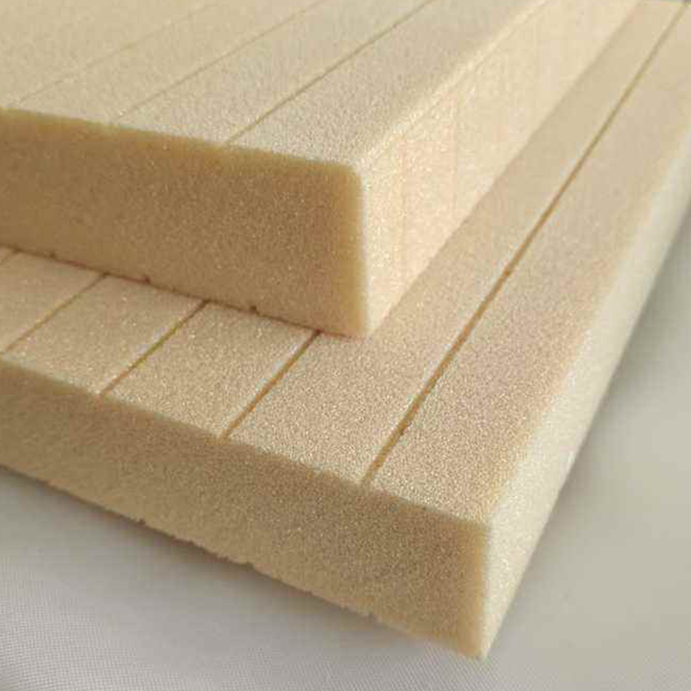
A Failure Analysis, Root Cause and Corrective Action Guide for Composite Engineers and Buyers
1. Introduction: When a Sandwich Panel Fails, the Core Is Not Always the Cause
PVC Foam Core Sandwich Panels are widely used in marine structures, wind turbine blades, transportation panels, building systems and industrial composite structures.
Their fundamental advantage is simple:
Lightweight Core + Stiff Face Sheets = High Structural Efficiency
However, a sandwich structure is not simply a face sheet bonded to a piece of foam.
Its actual performance depends on the interaction between:
- Face sheet stiffness
- PVC Foam Core density
- Core thickness
- Core shear strength
- Core shear modulus
- Core compression strength
- Adhesive or resin system
- Skin-core interface
- Core machining
- Laminate quality
- Manufacturing process
- Environmental conditioning
- Structural geometry
- Applied load
ASTM standards recognize this system-level relationship. ASTM C273/C273M addresses core shear properties, while ASTM C393/C393M evaluates sandwich construction behavior and can be used for core shear or core-to-facing shear assessment. ASTM C365/C365M addresses flatwise compression of sandwich cores.
Therefore, when a PVC Foam Core Sandwich Panel fails, the correct engineering question is not simply:
“Is the PVC Foam Core strong enough?”
The better question is:
“Which component or interface reached its governing failure mode first, and why?”
This article uses a failure-analysis framework to examine the most important failure modes in PVC Foam Core Sandwich Panels and translates those findings into practical material-selection, manufacturing-control and procurement decisions.
2. The Five-Level Failure Hierarchy
A sandwich panel can fail at several different structural levels.
| Level | Failure Location | Typical Failure |
|---|---|---|
| Level 1 | Face Sheet | Cracking, yielding, fiber failure |
| Level 2 | PVC Foam Core | Shear, crushing, cracking |
| Level 3 | Skin-Core Interface | Debonding, delamination |
| Level 4 | Geometry | Buckling, indentation, local instability |
| Level 5 | Manufacturing Defect | Void, resin-rich area, machining defect |
The same external symptom can have completely different root causes.
For example, a visible crack on the face sheet may actually originate from:
- core shear deformation,
- local indentation,
- skin-core debonding,
- insufficient core thickness,
- poor adhesive bonding,
- or local manufacturing defects.
This is why failure analysis must begin with the failure sequence, not only the final visible damage.
3. The Seven Major Failure Modes
For PVC Foam Core Sandwich Panels, the most important failure modes can be organized as follows:
- Core shear failure
- Core compression/crushing
- Skin-core debonding
- Face-sheet wrinkling
- Local indentation
- Global buckling
- Progressive fatigue damage
These failure modes can occur independently or interact with one another.
A typical failure sequence may look like:
Local Load
↓
Core Deformation
↓
Interface Stress Concentration
↓
Debonding
↓
Core Shear
↓
Face-Sheet Instability
↓
Progressive Structural Failure
The actual sequence depends on the sandwich configuration.
4. Failure Mode 1 — PVC Foam Core Shear Failure
Core shear is one of the most important failure mechanisms in sandwich construction.
The core maintains the distance between the face sheets and transfers transverse shear.
A simplified shear relationship is:
[
\tau = \frac{V}{A_c}
]
where:
- ( \tau ) = core shear stress
- ( V ) = applied shear force
- ( A_c ) = effective core shear area
When the applied shear stress exceeds the allowable core shear strength, the core can fail.
Typical Visual Appearance
Core shear may produce:
- diagonal cracks,
- localized core tearing,
- permanent deformation,
- interface separation,
- crushed foam around the failure zone.
Typical Root Causes
| Root Cause | Risk |
|---|---|
| Core density too low | High |
| Core thickness insufficient | Medium–High |
| Excessive transverse load | High |
| Poor core quality | High |
| Excessive machining | Medium |
| Local load concentration | High |
| Environmental degradation | Application dependent |
ASTM C273/C273M is specifically intended to determine core shear strength and shear modulus.
5. Core Shear Strength vs Core Shear Modulus
These properties are often incorrectly treated as the same thing.
They are not.
Core Shear Strength
Describes the stress level associated with shear failure.
Core Shear Modulus
Describes the core’s resistance to shear deformation.
| Property | Primary Engineering Meaning |
|---|---|
| Shear Strength | Ultimate shear capacity |
| Shear Modulus | Shear stiffness |
| High Strength | Delays catastrophic failure |
| High Modulus | Reduces deformation |
| Fatigue Performance | Depends on both + structure |
A panel can therefore have acceptable ultimate shear strength but excessive deformation because the core shear modulus is insufficient.
This distinction becomes particularly important in:
- long panels,
- wind turbine blades,
- marine decks,
- transportation floors,
- large architectural panels.
6. Failure Mode 2 — Core Crushing
Core crushing is different from core shear.
It generally occurs when the PVC Foam Core experiences excessive compressive stress.
Typical locations include:
- beneath concentrated loads,
- under fasteners,
- beneath supports,
- around inserts,
- under narrow load pads,
- at panel edges,
- around structural transitions.
ASTM C365/C365M is designed to determine flatwise compressive properties of sandwich cores, including compressive strength and modulus in the direction normal to the face sheets.
Simplified Crushing Model
[
\sigma_c = \frac{P}{A}
]
where:
- ( \sigma_c ) = local compressive stress
- ( P ) = applied load
- ( A ) = effective load-bearing area
If the actual load area becomes very small, local stress can become much greater than the average panel stress.
7. Why Low-Density PVC Foam Can Be Vulnerable to Local Crushing
A low-density core provides excellent weight efficiency.
But its lower compressive capacity can become a limitation under concentrated loads.
| Load Type | Low-Density Core | Medium-Density Core | High-Density Core |
|---|---|---|---|
| Distributed Load | Excellent | Excellent | Excellent |
| Point Load | Limited | Good | Very Good |
| Fastener Load | Limited | Good | Very Good |
| Insert Area | Usually requires reinforcement | Good | Excellent |
| Floor Loading | Application dependent | Good | Very Good |
| Heavy Equipment Support | Limited | Medium | High |
This leads to a fundamental design rule:
The core density should be selected according to the local load condition, not only the average panel load.
8. Failure Mode 3 — Skin-Core Debonding
Skin-core debonding is one of the most dangerous failure modes because the foam itself may remain apparently intact while the structural sandwich function has already been compromised.
The interface may fail because of:
- inadequate surface preparation,
- insufficient resin,
- excessive resin,
- adhesive voids,
- contamination,
- poor cure,
- excessive local stress,
- incompatible adhesive,
- core surface damage,
- core machining defects.
ASTM C393/C393M specifically notes that measured sandwich shear performance is affected by the facing material, core, adhesive, fabrication method, core geometry, density, adhesive thickness, specimen preparation, conditioning, environment and adhesive void content.
This is an important reason why a supplier’s bare PVC Foam Core shear strength cannot be treated as equivalent to the finished sandwich’s interface strength.
9. Why Debonding Is Particularly Dangerous
Consider two panels.
Panel A
Core shear strength = high
But:
Skin-core bond = poor
Panel B
Core shear strength = medium
But:
Skin-core bond = excellent
Under certain loading conditions, Panel A can fail earlier because the interface fails before the core reaches its nominal shear strength.
Therefore:
[
\text{Panel Strength} \neq \text{Core Strength Alone}
]
A more realistic model is:
[
P_{failure} =
\min(P_{face},P_{core},P_{interface},P_{buckling},P_{indentation})
]
The weakest governing mode determines the structural limit.
10. Failure Mode 4 — Face-Sheet Wrinkling
Face-sheet wrinkling is a local instability phenomenon.
It may occur when the face sheet is in compression and the supporting core does not provide sufficient stability.
Typical contributing factors include:
- insufficient core modulus,
- low core density,
- thin face sheet,
- inadequate bonding,
- local geometric imperfections,
- excessive compressive stress.
A sandwich panel may therefore have adequate core shear strength but still fail through face wrinkling.
Engineering Response
Possible solutions include:
- increasing core thickness,
- increasing core modulus,
- increasing face-sheet thickness,
- modifying laminate architecture,
- improving bonding,
- reducing local unsupported length.
11. Failure Mode 5 — Local Indentation
Indentation is particularly important when the panel is subjected to concentrated loading.
Typical examples:
- furniture panels,
- vehicle floors,
- marine decks,
- equipment platforms,
- cabinet panels,
- transportation flooring.
The failure may appear as a small depression, but the underlying core can be significantly damaged.
Typical Indentation Sequence
Point Load
↓
Face Sheet Local Bending
↓
Core Compression
↓
Plastic/Crushed Core Zone
↓
Permanent Dent
↓
Potential Delamination
12. Failure Mode 6 — Global Buckling
Global buckling is fundamentally different from core crushing.
The entire panel or a large structural section becomes unstable.
Typical causes include:
- excessive panel dimensions,
- insufficient sandwich thickness,
- insufficient face-sheet stiffness,
- inadequate edge support,
- compressive loading,
- geometric imperfections.
A simple engineering representation is:
[
P_{cr} \propto \frac{EI}{L^2}
]
where:
- (P_{cr}) = critical buckling load
- (EI) = structural bending stiffness
- (L) = characteristic unsupported length
Increasing sandwich thickness can significantly improve structural stiffness because it increases the distance between the face sheets.
13. Failure Mode 7 — Fatigue Damage
Static strength does not automatically indicate fatigue performance.
A sandwich panel used in:
- wind turbine blades,
- marine vessels,
- vehicles,
- railway structures,
- aircraft-related applications,
may experience millions of loading cycles.
A panel can therefore survive a static test but gradually accumulate:
- microcracks,
- interface damage,
- core shear deformation,
- debonding,
- delamination,
- local buckling.
Simplified Fatigue Progression
| Stage | Condition |
|---|---|
| 1 | Initial manufacturing condition |
| 2 | Micro-damage |
| 3 | Local stiffness reduction |
| 4 | Interface damage |
| 5 | Core cracking |
| 6 | Debonding propagation |
| 7 | Structural instability |
Fatigue must therefore be considered separately from static qualification.
14. Failure Mode Map
A useful engineering failure map is:
| Failure Mode | Primary Trigger | Secondary Trigger | Main Test |
|---|---|---|---|
| Core Shear | High transverse load | Low density | ASTM C273 |
| Core Crushing | Point load | Low compression strength | ASTM C365 |
| Debonding | Poor interface | Voids/contamination | ASTM C393/C297 |
| Wrinkling | Face compression | Low core modulus | Sandwich flexure |
| Indentation | Local load | Thin face/core | Compression/local load |
| Buckling | Global compression | Low stiffness | Structural test |
| Fatigue | Cyclic load | Defects | Fatigue testing |
This table is useful during both engineering design and supplier qualification.
15. Real Engineering Case — Wind Turbine Blade Sandwich Failure
Research on composite sandwich structures representative of wind turbine blades has demonstrated that core machining configuration and foam density can change both the strength and failure mode.
One study compared plain, double-grooved/perforated and grooved/perforated/cut configurations. Failure behavior changed from global buckling toward combinations of core shear and skin/core debonding, with the machining configuration influencing the final failure mechanism.
This is important because it demonstrates:
Machining is not merely a manufacturing detail. It can become a structural variable.
For a wind turbine blade supplier, the specification should therefore include not only:
PVC Foam Core Density
but also:
Groove + Perforation + Cutting Configuration
16. Real Engineering Case — Resin-Filled Groove Defects
Fractographic investigation of sandwich panels from a composite wind turbine blade identified partially resin-filled grooves that created large voids within the foam.
The study associated these defects with crack migration and skin/core debonding.
This provides an important manufacturing lesson.
A groove is designed to improve:
- resin flow,
- vacuum infusion,
- core conformity.
But if the groove geometry or infusion process is poorly controlled, it can become a structural defect.
Therefore:
The objective is not maximum resin flow. The objective is controlled resin flow without creating excessive resin-rich or void-containing regions.
17. Real Engineering Case — Tapered PVC Foam Core
Tapered sandwich structures are commonly used in wind turbine blade transitions.
Recent experimental and numerical research found that taper slope can significantly influence:
- static strength,
- fatigue life,
- failure mode,
- crack propagation.
The study evaluated 11°, 18° and 45° taper configurations and found substantial differences in structural response.
This reinforces a broader principle:
Geometry is part of material performance.
A PVC Foam Core supplier capable of producing a nominally correct density but poorly controlled taper geometry may still create a structurally inferior component.
18. Root Cause Analysis: The 5M Framework
When a sandwich panel fails, a useful root-cause framework is the 5M method.
Material
- Incorrect density
- Density variation
- Poor cell structure
- Contamination
- Moisture/environmental degradation
Machine
- Incorrect CNC settings
- Cutting damage
- Groove depth variation
- Perforation inconsistency
Method
- Incorrect bonding
- Insufficient resin
- Excess resin
- Incorrect vacuum pressure
- Incorrect curing
Man
- Handling damage
- Incorrect assembly
- Incorrect inspection
- Installation errors
Measurement
- Inadequate testing
- Incorrect sampling
- Wrong test method
- Insufficient traceability
This method prevents engineers from automatically blaming the foam material.
19. Material Root Cause vs Process Root Cause
A common mistake is:
Panel Failed → Foam Is Weak
But the actual chain could be:
Panel Failed
→
Interface Debonding
→
Void in Adhesive
→
Insufficient Resin Flow
→
Incorrect Groove Geometry
→
Machining Variation
→
Process Control Failure
In this scenario, changing from 80 kg/m³ PVC Foam Core to 100 kg/m³ PVC Foam Core may not solve the real problem.
This is why failure analysis should identify the first initiating defect.
20. Diagnostic Matrix for Failed PVC Foam Core Panels
| Observation | Possible Root Cause | Recommended Investigation |
|---|---|---|
| Diagonal core crack | Core shear | C273 + microscopy |
| Vertical crushing | Compression | C365 |
| Clean interface separation | Debonding | Interface inspection |
| Resin-rich groove | Poor infusion | Cross-section |
| Large internal void | Vacuum/resin problem | CT or sectioning |
| Face wrinkle | Local instability | Laminate/core analysis |
| Permanent dent | Indentation | Local compression |
| Edge delamination | Edge sealing/bonding | Edge inspection |
| Repeated fatigue cracks | Cyclic damage | Fatigue analysis |
| Uneven panel stiffness | Density/thickness variation | Mapping |
21. Non-Destructive Inspection Strategy
For critical composite sandwich panels, inspection should not stop at visual examination.
Possible techniques include:
- Visual inspection
- Tap testing
- Ultrasonic inspection
- Thermography
- X-ray imaging
- X-ray computed tomography
- Dimensional measurement
- Density mapping
The appropriate technique depends on:
- panel thickness,
- material system,
- defect type,
- production volume,
- criticality.
For example, internal voids in a grooved PVC Foam Core may not always be visible from the outside.
22. Recommended Failure Investigation Sequence
When a panel fails, follow a controlled sequence.
Step 1 — Preserve the Failure Area
Do not immediately cut or repair the damaged area.
Step 2 — Photograph the Failure
Record:
- location,
- direction,
- dimensions,
- surrounding geometry.
Step 3 — Identify the Failure Mode
Determine whether it is:
- core failure,
- interface failure,
- face failure,
- buckling,
- indentation.
Step 4 — Section the Structure
Inspect the internal failure path.
Step 5 — Compare With Manufacturing Records
Check:
- core batch,
- density,
- thickness,
- machining,
- resin,
- adhesive,
- cure cycle.
Step 6 — Repeat Targeted Testing
Do not simply repeat the same test.
Choose the test that investigates the suspected root cause.
23. Testing Strategy for Failure Analysis
| Investigation Objective | Recommended Test |
|---|---|
| Core shear | ASTM C273/C273M |
| Sandwich shear | ASTM C393/C393M |
| Core compression | ASTM C365/C365M |
| Facesheet properties | ASTM D7249/D7249M |
| Sandwich stiffness | ASTM D7250/D7250M |
| Dimensional stability | ASTM D6772/D6772M |
| Interface tensile behavior | ASTM C297/C297M |
| Fatigue | Application-specific cyclic test |
| Environmental durability | Conditioned mechanical testing |
ASTM’s current composite standards listing includes C273/C273M, C393/C393M, C365/C365M, D7249/D7249M, D7250/D7250M and D6772/D6772M among the relevant sandwich construction standards.
24. Why ASTM C273 and C393 Should Not Be Confused
This is a frequent procurement problem.
ASTM C273
Primarily characterizes:
Core shear properties
ASTM C393
Evaluates:
Sandwich construction under beam flexure
and can provide information related to:
- core shear,
- core-to-facing shear,
- sandwich stiffness,
- load-deflection behavior.
ASTM specifically states that C273 is preferred for core shear strength and modulus when bare core is available, while C393 is useful for sandwich-level behavior and bonded panel quality control.
Therefore, a supplier saying:
“Our PVC Foam Core passed C393”
does not necessarily provide the same information as a properly documented C273 bare-core result.
25. Engineering Acceptance Criteria
A useful acceptance system should have three levels.
Level A — Material Acceptance
Check:
- Density
- Thickness
- Appearance
- Compression
- Shear
- Dimensional tolerance
Level B — Process Acceptance
Check:
- Machining
- Resin compatibility
- Bonding
- Infusion
- Cure
Level C — Structural Acceptance
Check:
- Static strength
- Stiffness
- Fatigue
- Environmental conditioning
- Damage tolerance
A material should not be approved for structural production simply because Level A has passed.
26. Procurement Decision: What Should Be Specified?
A weak purchase specification might say:
PVC Foam Core, 80 kg/m³, 20 mm.
A stronger engineering specification should include:
Material
PVC Foam Core
Density
Target + tolerance
Thickness
Nominal + tolerance
Mechanical
- Compression strength
- Compression modulus
- Shear strength
- Shear modulus
Machining
- Groove depth
- Groove spacing
- Perforation diameter
- Perforation spacing
- CNC contour tolerance
- Taper angle
Surface
- Surface condition
- Bonding compatibility
- Cleanliness
Quality
- Batch number
- Test report
- Inspection report
- Traceability
27. Supplier Evaluation Based on Failure Risk
A more advanced supplier scorecard can be structured around failure prevention.
| Category | Weight |
|---|---|
| Core Mechanical Consistency | 15% |
| Density/Thickness Control | 10% |
| Machining Accuracy | 15% |
| Bonding Surface Quality | 10% |
| Manufacturing Traceability | 10% |
| Structural Test Data | 10% |
| Fatigue Data | 10% |
| Process Support | 5% |
| Production Capacity | 5% |
| Corrective Action Capability | 10% |
| Total | 100% |
The addition of Corrective Action Capability is important.
A good supplier should be able to investigate a failure rather than simply replace the material.
28. What a Strong Supplier Should Provide After a Failure
When a batch-related problem occurs, the supplier should ideally provide:
- Batch identification
- Production records
- Density data
- Thickness records
- Mechanical test results
- Machining records
- Raw material traceability
- Root-cause analysis
- Corrective action
- Preventive action
This is essentially a supplier-side CAPA system:
Corrective Action + Preventive Action
For large composite programs, this capability can be more valuable than a small difference in unit price.
29. Failure Prevention Through Design
Failure analysis should eventually feed back into design.
For example:
Problem
Core shear failure
Corrective Design
Increase:
- density,
- thickness,
- shear area,
- or local reinforcement.
Problem
Core crushing
Corrective Design
Increase:
- local density,
- load-bearing area,
- insert reinforcement.
Problem
Debonding
Corrective Design
Improve:
- surface preparation,
- adhesive,
- resin flow,
- cure,
- interface geometry.
Problem
Buckling
Corrective Design
Increase:
- sandwich thickness,
- face-sheet stiffness,
- core modulus,
- structural support.
30. Failure Prevention Through Manufacturing
Many sandwich failures can be prevented before the final structural test.
| Manufacturing Stage | Key Control |
|---|---|
| Core cutting | Dimensional accuracy |
| CNC machining | Groove/taper tolerance |
| Cleaning | Surface contamination |
| Layup | Core positioning |
| Resin infusion | Flow distribution |
| Vacuum bagging | Leak control |
| Bonding | Adhesive thickness |
| Curing | Temperature/time |
| Demolding | Core damage |
| Final inspection | Defect detection |
The engineering objective should be:
Control the process that creates the structure, not merely inspect the structure after it has been created.
31. A Practical Failure Prevention Matrix
| Failure | Material Solution | Process Solution | Design Solution |
|---|---|---|---|
| Core Shear | Higher shear grade | Avoid core damage | Increase thickness/density |
| Crushing | Higher compression grade | Improve handling | Local reinforcement |
| Debonding | Better bonding surface | Improve infusion | Increase interface area |
| Wrinkling | Higher modulus core | Better bonding | Increase skin/core support |
| Indentation | Higher density | Improve load distribution | Add local reinforcement |
| Buckling | Higher stiffness | Better geometry | Increase sandwich depth |
| Fatigue | Qualified grade | Reduce defects | Optimize load path |
32. The “Wrong Material” vs “Wrong Application” Problem
PVC Foam Core is available in multiple densities and structural grades.
A failure does not necessarily mean that PVC Foam Core is unsuitable.
It may mean that:
- the density was too low,
- the thickness was insufficient,
- the machining pattern was inappropriate,
- the bonding process was poor,
- the load was incorrectly estimated,
- or the panel geometry was inadequate.
Therefore:
Material Failure
and
Material Selection Failure
are different concepts.
33. Procurement Red Flags Related to Failure Risk
Buyers should be cautious if a supplier:
- provides only density data;
- provides no mechanical test standard;
- provides no test direction;
- provides no conditioning information;
- cannot explain density tolerance;
- cannot control groove depth;
- cannot control perforation geometry;
- cannot supply tapered sections;
- cannot provide batch traceability;
- has no failure-analysis capability;
- cannot provide production samples;
- cannot distinguish core shear from interface failure.
A technically mature supplier should be able to discuss failure modes, not just product specifications.
34. Recommended Qualification Program Before Mass Production
A practical program can be organized into five stages.
Stage 1 — Raw Core
Test:
- Density
- Thickness
- Compression
- Shear
Stage 2 — Machined Core
Test:
- Groove geometry
- Perforation
- Taper
- Dimensional tolerance
Stage 3 — Small Sandwich Panel
Test:
- Bonding
- Flexure
- Core shear
- Interface failure
Stage 4 — Representative Component
Test:
- Static load
- Local load
- Compression
- Damage tolerance
Stage 5 — Full Structural Validation
Test:
- Fatigue
- Environmental exposure
- Full-scale structural loading
This progressive approach reduces qualification cost while increasing confidence.
35. Engineering Decision Matrix
When a failure occurs, engineers can use the following decision sequence.
Question 1
Did the PVC Foam Core itself fail?
Yes → investigate density, shear and compression.
No → continue.
Question 2
Did the interface fail?
Yes → investigate bonding and resin.
No → continue.
Question 3
Did the face sheet fail?
Yes → investigate laminate design.
No → continue.
Question 4
Did the structure buckle?
Yes → investigate stiffness and geometry.
No → continue.
Question 5
Did manufacturing defects initiate the failure?
Yes → implement process correction.
This prevents premature material substitution.
36. Final Procurement Checklist
Before approving a PVC Foam Core supplier for a structural application, buyers should confirm:
Material
- Density specification
- Density tolerance
- Thickness tolerance
- Core shear data
- Compression data
- Dimensional stability
Manufacturing
- Groove capability
- Perforation capability
- CNC cutting
- Taper machining
- Surface preparation
- Dimensional inspection
Structural
- Sandwich test data
- Interface data
- Fatigue information
- Environmental data
- Representative samples
Quality
- Batch traceability
- Inspection records
- Test reports
- Corrective-action system
- Production consistency
Commercial
- Production capacity
- Lead time
- Packaging
- Technical support
- Total cost of ownership
37. Conclusion: Failure Analysis Should Change How PVC Foam Core Is Purchased
The most important lesson from PVC Foam Core Sandwich Panel failure analysis is that failure rarely has only one variable.
Core density matters.
Core thickness matters.
Core shear strength matters.
Core compression strength matters.
But so do:
- machining,
- resin distribution,
- adhesive thickness,
- interface quality,
- face-sheet design,
- structural geometry,
- environmental conditions,
- manufacturing consistency.
Research on wind turbine blade sandwich structures demonstrates that core machining configuration can change both strength and failure mode, while studies of tapered PVC Foam Core structures show that transition geometry can significantly influence crack propagation, static strength and fatigue behavior.
The correct engineering philosophy is therefore:
Do not ask only whether the PVC Foam Core is strong enough. Ask which failure mode is expected to govern, how that failure will initiate, how it will propagate, and how the supplier controls the variables that influence it.
For engineers, this creates a more reliable design methodology.
For manufacturers, it creates a stronger quality-control system.
For procurement teams, it changes supplier evaluation from:
Price + Density
to:
Mechanical Performance + Manufacturing Consistency + Failure Prevention + Traceability + Total Cost of Ownership
That is the more appropriate framework for selecting PVC Foam Core for demanding composite sandwich structures.
